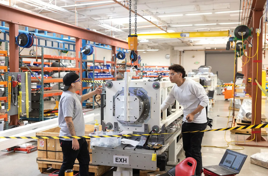
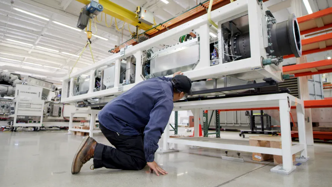
Technicians work on the frame of a linear generator core. CREATIVE SHOT
It’s January 2030 and your electric heat pump is warming the house while your electric car charges in the garage, all powered by solar panels on your roof and by wind and solar generators at your local utility. It doesn’t matter that it’s been raining for two weeks because your utility is tapping into ammonia produced with last summer’s sunshine. It’s consuming that ammonia in a linear generator.
The linear generator can quickly switch between different types of green (and not-so-green, if need be) fuel, including biogas, ammonia, and hydrogen. It has the potential to make the decarbonized power system available, reliable, and resilient against the vagaries of weather and of fuel supplies. And it’s not a fantasy; it’s been developed, tested, and deployed commercially.
The cofounders of Mainspring Energy, of which I am one, spent 14 years developing this technology, and in 2020 we began rolling it out commercially. It is currently installed at tens of sites, producing 230 to 460 kilowatts at each. We expect linear generators at many more locations to come on line within the next year.
It started at Stanford
The story of the linear generator began nearly two decades ago at Stanford University’s Advanced Energy Systems Laboratory, when mechanical engineering professor Christopher Edwards asked some of us Ph.D. students a simple question: “What is the most efficient and practical way possible to convert chemical-bond energy into useful work?”
We started by considering fuel cells, since they can be very efficient. But fuel cells use catalysts to trigger the chemical reactions that release energy, and catalysts typically cost a lot, degrade over time, and respond poorly to rapid changes in load. So we began looking for an alternative.
We knew that we could trigger the release of energy simply by compressing a mixture of air and fuel. Here’s how that would work.

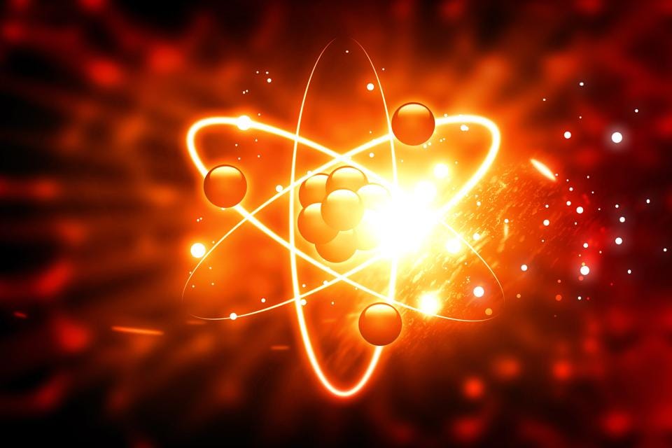
The efficient, clean, flameless reaction at the heart of the Mainspring generator works with nearly any fuel, including carbon-free ammonia as shown here. The ammonia reacts with oxygen in air to produce nitrogen gas and water, and the resulting force pushes against the walls of the box. MAINSPRING
First, fuel and air enter a closed chamber with movable end walls. Next, those end walls move toward each other, compressing the mixture of fuel and air. As this happens, the molecules within the mixture collide faster and faster, until they at last break apart and re-form into different molecules, releasing the energy stored in their chemical bonds. That energy causes the new molecules to collide even faster and more often, not just with themselves but also with the walls of the chamber, raising the pressure in the chamber. It all happens without a spark or any other ignition source.
The pressure pushes the walls outward with more force than that needed to push them inward at the beginning of the cycle. Once these walls reach their initial position, and the pressure within the chamber reverts to its initial state, a new batch of fuel and air flows in, pushing the molecules created by the previous cycle out of the chamber and starting the process all over. That’s the theory. To test it out, in 2008 we constructed an apparatus capable of compressing through a volume 100 times that of the starting value, then expanding back again. We used a metal tube two meters long and 50 millimeters in diameter, with a closed wall on one end and a metal slug as the moving wall. This arrangement works like a piston that compresses a gas inside a cylinder in an engine, although that’s where the similarities end—the “piston” in our device was not attached to a crankshaft, or to anything at all. I’ll discuss in a moment the limitations of this type of engine architecture for this kind of reaction, and how we solved them with a new type of machine. But it was a good place to start.
Our first device was very simple—it could run only one “shot” at a time, and it did not produce electricity; that is, we did not harvest the energy produced. But we could use it to measure the efficiency of the reaction, meaning the extra push that must be applied to the moving wall during expansion relative to how much fuel was used. And the results were excellent, the device was efficient as a fuel cell, just as we had hoped. Now we had to build a version that could generate electricity and run for years at a reasonable cost. In 2010, Shannon Miller, Adam Simpson, and I incorporated Mainspring Energy to build a real-world system. Khosla Ventures provided our initial seed money; to date we’ve raised more than US $500 million from a range of investors, including Khosla, American Electric Power, Bill Gates, and NextEra Energy.
Generators that use the flameless compression reaction had been built before in research labs, based on a conventional combustion-engine architecture, but they were limited by the difficulty of controlling the reaction in this type of apparatus. To be efficient, the mixture needs to be compressed just enough to initiate the reaction. If compression continues after the reaction happens, it fights against the pressure generated by the reaction, wasting energy. If compression stops too soon, the reaction never happens.
This optimal compression varies with conditions, beginning with the choice of fuel: Hydrogen, for example, reacts with less compression than ammonia. Running at a partial power output instead of full power or running on a hot day versus a cold one, also changes the optimal compression.
A conventional engine harvests energy when the extra pressure generated from the reaction pushes on a piston, which pushes on a connecting rod to rotate a crankshaft. The crankshaft geometry constrains the piston to always follow the same motion, and therefore the same amount of compression, no matter what. Such an engine can’t adapt to changes in the required compression, and that makes it hard to control the reaction.
So rather than mimicking an engine, we designed a new machine that ties the compression and expansion motion directly to the generation of electricity, and in doing so provides the necessary reaction control. This machine ended up looking completely different from—and having almost no parts in common with—a conventional engine. So we felt a new name was needed, and we called it the linear generator.
How the linear generator works
Picture a series of five cylindrical assemblies arranged in a line, held within a boxlike frame. The central tube is the reaction chamber; it’s where the fuel and air go. On either side of it sits a linear electromagnetic machine (LEM) that converts the push from pressure directly into electric power. At each end of the generator is an air-filled cylindrical chamber that acts as a spring to bounce the moving part of the LEM back to the center. The whole arrangement—two air springs, two LEMS, and a reaction chamber—forms a linear generator core. It’s long and skinny: A machine rated at 115 kW is about 5.5 meters long and about 1 meter high and wide.
The LEM, in principle, is an electric motor that has been unrolled to form a line instead of a circle. It consists of a moving part—the translator—and a stationary part—the stator. The translator is a long, straight tube with an array of neodymium permanent magnets attached to the perimeter, near the center. An end plate caps each translator tube and seals to the inner surface of the reaction chamber. The capped end of the translator does the actual compression, as the piston would in an engine, but it is wildly different in design. The stator is a series of copper coils. As the translator moves back and forth in a straight line inside the coils, the magnets generate current that feeds an 800-volt DC bus.
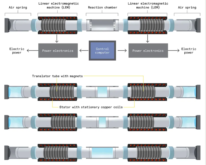
In Mainspring’s linear generator, two translators move within a center reaction zone located between two outer air springs. A set of stationary copper coils surrounds each translator, forming a linear electromagnetic machine (LEM). A cycle begins with the introduction of air and fuel into the center reaction zone. Energy stored in the air springs from a previous cycle compresses the mixture until a flameless reaction occurs. The reaction drives the translators, to which magnets are attached, back through the copper coils, producing electricity. The force of this motion also compresses the air springs, readying the system for the next cycle.MAINSPRING
It works rather like regenerative braking. An electric car’s motor acts in reverse, as a generator, to convert the car’s motion into electricity, to feed the batteries. Here, the LEM converts the translator’s kinetic energy into electricity.
Our control computer immediately adjusts the flow of current through the coils via an array of power-switching transistors to make the LEM apply more or less force. The LEM can hit a desired turnaround position within about 1/10th of a millimeter, then target and hit a different turnaround position on the next cycle. The system determines a turnaround position at which the level of compression triggers the reaction just before the end of the stroke, the most efficient point.
This ability to automatically and rapidly adjust compression is remarkable in two ways.
First, the generator maintains the optimum reaction process throughout the entire load range, from idle all the way to full power, in order to follow demand. For example, if power demand drops, the fuel will flow more slowly and the fuel molecules will thus be a little more dilute; they’ll need a little more compression, and our system will provide just the right amount.
One real-world example of the system working this way pairs our generators with a 3.3-megawatt rooftop solar array. When the sun is shining, our generators turn off, and when the sun goes down or goes behind a cloud, our generators automatically turn on within seconds, immediately providing precisely as much power as the building requires.
Providing the compression that’s needed, just when it’s needed, also unlocks the capability to operate efficiently using fuels that have widely different properties. For example, hydrogen reacts with little compression, but ammonia requires a lot. The linear generator is fuel agnostic—it can run a wide range of fuels including natural gas, biogas, hydrogen, ammonia, syngas, and even alcohols without compromising performance.
That’s the LEM. The remaining pieces of the architecture came about as we worked to maintain the inherent efficiency of the reaction in a real machine that has minimal losses like friction and heat transfer while running reliably for billions of cycles.
Figuring out the generator’s design
One of the biggest choices we had to make was the overall layout of the machine. We knew that the pressurized gas had to push on a moving wall directly connected to an electromagnetic force, but there were several ways to make that happen. In the first year or so we founders, together with seven other engineers, spent many hours at a whiteboard considering our options. Ultimately, we chose a symmetrical layout with two translators meeting in a single, central cylinder. Our fuel-air mixture, slightly pressurized, enters through the holes on one end. When the translators move away from that end, these holes are uncovered, and because the fresh mixture is at slightly higher pressure, it flows into the cylinder, pushing the used materials out the holes on the other end.
This choice replaces the conventional engine valve train—valves, seats, guides, seals, springs, rockers, camshaft, bearings, timing chain, and oil lubrication—with a simple set of holes in the cylinder wall. Another advantage of combining two translators in a single cylinder is the reduction of heat-transfer losses by nearly half.
On the Manufacturing Floor

A technician at one of Mainspring Energy's facilities in Menlo Park, Calif., routes compressed air from an air spring to a generator’s bearingsCREATIVE SHOT
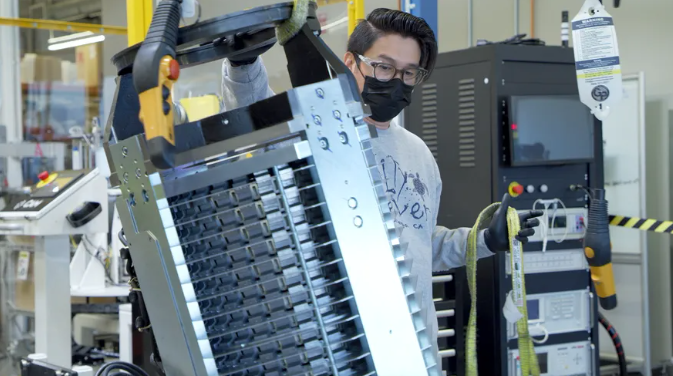
A stator is positioned in preparation for assemblyMAINSPRING
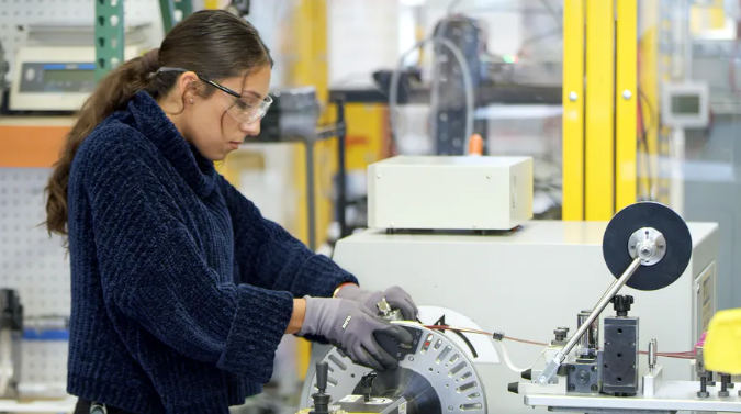
A technician prepares copper wires to be wound into coilsMAINSPRING
A gantry moves a completed core across the manufacturing floor for final assembly MAINSPRING
Our last major design choice was to add an air chamber to either end of the generator. As the translators move outward during the expansion portion of the cycle, the outer ends of the translators compress plain air in the outer chambers, thus storing a fraction of the reaction energy. This stored energy is recovered afterward, when the compressed air pushes the translators back toward the center to start the next compression cycle. It’s the same idea as storing energy by compressing and releasing a mechanical spring. This way, the LEMs can apply their braking forces and generate power in both directions, allowing us to cut their size by half.
We also let a small amount of this pressurized air out of our system to feed air bearings. Compared with oil-lubricated bearings, air bearings have lower friction and simpler seals. They work just like an air hockey game, where an array of small holes creates a pressurized film of air on which the puck floats.
A prototype turns on the lights
In 2012, about a year and a half after our initial round of $10 million, we completed the first prototype that generated power. It put out only 1 kW.
A couple of days after we had gotten it to work for the first time, one of our investors let us know that he was planning to drop by our Menlo Park, Calif., headquarters to see it run. The engineer who had done most of the electrical design realized that, for a demo, we needed a way to see it making power, so he ran out to a nearby hardware store, bought a couple of halogen work lights, and plugged them directly into the electrical bus. Though barely more impressive than the school science project in which a potato powers a light bulb, it proved that our design worked.
But the output was a long way from our commercial target, 200 kW, a number we had picked because it would provide enough power for a typical retail store.
A bigger version stumbles
Our next milestone came in late 2013, when we built a 50-kW machine. And…it didn’t work at all.
It had a teething problem not uncommon with large power equipment. An array of coils switching high voltage at a relatively high frequency generates a lot of electrical noise. In our device, it fed back to our position sensor and caused the LEM to vibrate, creating a sound we called “the crunchies.” Our electrical and controls engineers were able to work through the problem and eliminate it.
But then we hit a wall—literally: The side of the translator would scrape along the cylinder wall whenever we tried to produce more than a few kilowatts.
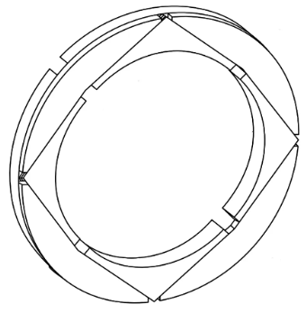
The overlapping segments in Mainspring’s patented sealing design allow the ring to maintain its efficiency even as it wears. The device requires no added lubricant. MAINSPRING
To explain what happened, I need to describe one more component of our linear generator: the seal between the translator and the cylinder wall. This seal exists to keep the pressurized gas from escaping while still allowing the translator to slide.
Typically, you would use a layer of liquid oil between the two parts to avoid friction. But remember, we’re adding fresh air and fuel into the cylinder through holes in the cylinder wall, and if we used a liquid lubricant in this arrangement, it would be nearly impossible to keep it from getting into the fuel mix and burning during the reaction process, creating noxious emissions.
So we decided to develop an oil-free sealing system. It worked well in our 1-kW device, and so we scaled the same design up for the 50-kW model. But though the machine got larger, the clearance requirements stayed the same in an absolute sense and thus were tighter in a relative sense. That allowed tiny distortions in the components to create points of friction, causing further distortions, ending with a runaway scraping problem.
After months of trying various tweaks, we still couldn’t run beyond around 20 percent of full power without scraping. So we threw out the old sealing design and started over. We ended up inventing a unique carbon sealing-ring assembly that floats independently from the translator, one that can expand as it wears down, thus maintaining its seal.
This fixed the problem, and within a few more months we were running at full power for hundreds of hours. The next big scaling step—from 50 kW to 100 kW—was less difficult and culminated in our first official prototype, which we installed in the parking lot behind our building.
Making the linear generator affordable
We still needed to make the linear generator affordable. The technology had the advantage of using fewer parts than engines or turbines and lacking the expensive catalyst of fuel cells. But we had to figure out package design, engineering for high-volume manufacturing, and the supply chain for a product we decided would consist of two side-by-side linear generators for a total power of 230 kW. We made a few mistakes along the way.
One big one involved our efforts to reduce the cost of physically attaching the magnet array to the outside of the translator tube. In the prototypes, we secured the magnets against the tube by winding resin-impregnated Kevlar fiber around the outside of the glued-on magnets. In our first attempt at cost reduction we switched to an impregnated cloth wrap that went on more quickly and easily, but after building a couple of units with this approach we discovered that magnets were coming loose under the wrap. So we went back to the wound-Kevlar approach, and eventually reduced its cost by developing an automated winding process.
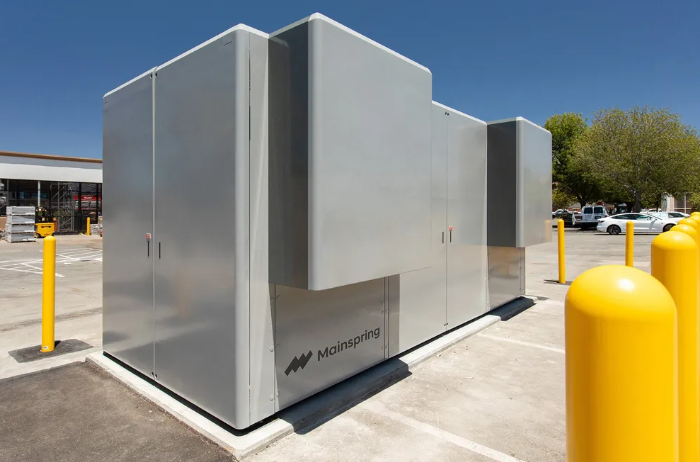
Mainspring Energy’s first commercial product contains two linear generator cores. This unit, installed outside a store in Northern California, can produce up to 230 kilowatts of power.MAINSPRING
Linear generation reaches the real world
Finally, in June 2020, in the thick of the COVID pandemic, a crew pulled a flatbed truck up to our Silicon Valley headquarters, loaded up the first-in-the-world production linear generator, and drove it 30 kilometers to a paying customer’s site—part of a national retail chain. A couple of days later we flipped the switch, and we were in business! A few months later we delivered our second unit to a Kroger store in Southern California, and shortly after that a pair of units went to a Lineage Logistics cold-storage facility.
When we started the company, we optimized the first generator for natural gas because it was then most widely available, least expensive, and relatively clean. Even though it does produce carbon emissions, our system’s efficiency makes it greener than the traditional generators that it replaces.
We see our linear generator as the cornerstone of a zero-carbon grid because of its unique flexibility: it can handle nearly any scale of power, from single units to grid-connected arrays; it’s easily permitted and installed wherever power is needed; and it runs on almost any fuel. We have run one of our stock units on hydrogen and on anhydrous ammonia. We have a customer project running on renewable biogas in a landfill. We plan to start operating other biogas projects at wastewater treatment plants and dairy waste digesters this year. We are getting ready to deploy arrays of up to dozens of generators for large-scale operations, like electric-truck charging. And we are now designing larger, utility-scale versions in the megawatt output range. These will all use the same core technology without any radical design changes.
And yes, Professor Edwards, we think we have answered that question you posted some 20 years ago: “What is the most efficient and practical way possible to convert chemical-bond energy into useful work?” It’s the linear generator.